Brief introduction:
The gas cylinder is easy to use, safe and reliable, economical and durable. The special features are as follows
1.The support system of the inner tank is made of stainless steel to achieve the purpose of low heat loss and high strength.
2. It is easy to use and can be operated independently by a single person.
3. Store pure cryogenic liquid. Large storage capacity. The gas storage capacity of a DP175 Dewar cylinder is equivalent to more than 18 times the gas storage capacity of a standard high-pressure gas cylinder.
4. The internal pressure of the gas cylinder will rise during the deactivation phase after filling. The gas cylinder has a high-performance insulation system, and its pressure rise rate is low. Under normal circumstances, there is no need to reduce the pressure through a safety valve.
5. The built-in supercharger and vaporizer can realize continuous supply of gas or liquid, and there is no need to install an external vaporizer under the designed dosage.
Main Features:
1. High vacuum insulation technology is applied to achieve higher cost performance.
2. Ultrasonic fault detection, high quality inspection.
3. Level gauge and pressure gauge on all tanks
4. Famous brand pressure relief valve
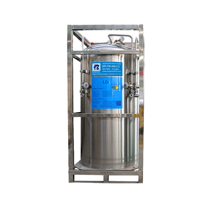
Dewar Cylinder Main Technical Parameters:
Full Volume:50L/80L/100L/175L/195L/210L/230L/240L/410L/450L/500L/1000L
Work Pressure: 1.37MPa/2.3MPa/2.88MPa/3.45MPa
Inner Tank Design Temperature: -196
Shell Tank Design Temperature: -20℃~+50℃
Insulation: Vacuum with Multi-layer Wrapped
Stored Medium: LO2,LN2,LAr,LCO2,LNG
Inner Tank Material: SS304 08 or SA240
Shell Tank Material: Q345R or SS304 08
Qualification Certification:
ASME VIII DIV.1, CE PED/TPED, Russia EAC, China GB, ISO9001:2015,ISO13485:2016, ISO14001:2015, ISO45001:2018
Product Information:
| Overall Size and Main Technical Parameters | |||||||||||||||
| Type | Nominal volume (L) |
Working pressure (MPa) |
Empty weight (Kg) |
Maximum theoretical liquid filling capacity(Kg) | Gas cylinder size (mm) |
Safety valve (MPa) |
Rupture disk (MPa) |
Filling weight(Kg) (±2KG) |
|||||||
| LNG | LO2 | LN2 | LAr | LCO2 | LO2 | LN2 | LAr | LCO2 | |||||||
| DPL Series – Vertical Cylinders | 50 | 2.3 | 76 | 19 | 53 | 37 | 65 | 51 | φ516*747 | 2.62 | 3.6 | 50 | 34 | 60 | / |
| 80 | 2.3 | 85 | 31 | 87 | 62 | 107 | 84 | φ516*907 | 2.62 | 3.6 | 80 | 56 | 98 | 78 | |
| 100 | 2.3 | 95 | 38 | 120 | 77 | 133 | 105 | φ516*1037 | 2.62 | 3.6 | 100 | 70 | 123 | 97 | |
| 175 | 1.37 | 116 | 67 | 190 | 135 | 233 | 183 | φ516*1507 | 1.59 | 2.4 | 175 | 121 | 213 | 169 | |
| 2.3 | 133 | 2.41 | 3.6 | ||||||||||||
| 2.88 | 146 | 3.45 | 5.17 | ||||||||||||
| 3.45 | 164 | 4.14 | 5.17 | ||||||||||||
| 195 | 1.37 | 125 | 75 | 212 | 150 | 260 | 204 | φ516*1632 | 1.59 | 2.4 | 196 | 136 | 239 | 190 | |
| 2.3 | 145 | / | 2.41 | 3.6 | |||||||||||
| 2.88 | 158 | 3.45 | 5.17 | ||||||||||||
| 3.45 | 185 | 4.14 | 5.17 | ||||||||||||
| 210 | 1.37 | 135 | 81 | 228 | 162 | 280 | 220 | φ516*1717 | 1.59 | 2.4 | 207 | 144 | 252 | 200 | |
| 2.3 | 150 | / | 2.41 | 3.6 | |||||||||||
| 2.88 | 166 | 3.45 | 5.17 | ||||||||||||
| 3.45 | 191 | 4.14 | 5.17 | ||||||||||||
| 230 | 2.01 | 180 | 85 | 244 | 170 | 298 | 237 | φ666*1333 | 2.41 | 3.6 | 236 | 164 | 288 | 229 | |
| 240 (small cart) |
1.37 | 185 | 84 | 242 | 168 | 295 | 234 | 800*800*1248 | 1.59 | 2.41 | 242 | 168 | 295 | 234 | |
| 2.3 | 213 | / | 2.62 | 3.6 | |||||||||||
| 3.17 | 240 | 3.45 | 5.17 | ||||||||||||
| 410 | 1.37 | 325 | 157 | / | / | / | / | 890*870*1770 | 1.59 | / | 413 | 287 | 504 | 400 | |
| 450 | 1.37 | / | 488 | 345 | 599 | 471 | 890*870*1850 | 1.59 | / | 453 | 315 | 553 | 439 | ||
| 2.3 | 370 | 2.41 | 3.6 | ||||||||||||
| 3.17 | 425 | 3.45 | 5.17 | ||||||||||||
| 500 | 1.37 | 360 | 192 | 542 | 384 | 665 | 523 | 890*870*2000 | 1.59 | / | 486 | 338 | 593 | 471 | |
| 2.3 | 407 | / | 2.41 | 3.6 | |||||||||||
| 3.17 | 448 | 3.45 | 5.17 | ||||||||||||
| 1000 | 2.3 | 1033 | / | / | 454 | 904 | 891 | φ1200*2182 | 2.6 | 3.6 | 1009 | 702 | 1231 | 978 | |
| 3.45 | 297 | 764 | 828 | 4.0 | 5.4 | ||||||||||
| DPW Series – Horizontal Cylinders |
410 | 1.59 | 342 | 158 | / | / | / | / | 1850*820*1020 | 1.9 | 2.4 | 413 | 287 | 504 | 400 |
| 499 | 1.59 | 353 | 192 | 541 | 383 | 664 | 522 | 2100*820*1020 | 1.9 | 2.4 | 503 | 350 | 614 | 488 | |
| 2.1 | 406 | / | 2.86 | 3.6 | |||||||||||
| 2.5 | 420 | 2.86 | 3.6 | ||||||||||||
| 3.45 | 510 | 4.15 | 5.17 | ||||||||||||
| 1000 | 1.59 | 585 | / | 1664 | 1330 | 1882 | / | 2100*1172*1400 | 1.9 | 2.4 | 977 | 679 | 1192 | 947 | |
| Note: The maximum filling capacity is calculated based on the boiling point of the liquid under normal atmospheric pressure. The actual filling capacity is affected by the liquid temperature and pressure inside the container, which is about 95% of the maximum theoretical filling capacity, and about 90% for natural gas. | |||||||||||||||
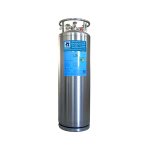
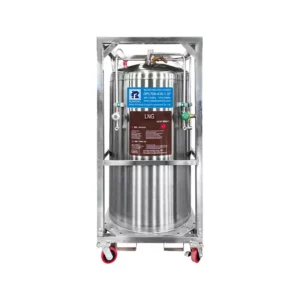
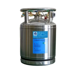
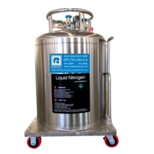
The structure of the Dewar Cylinder
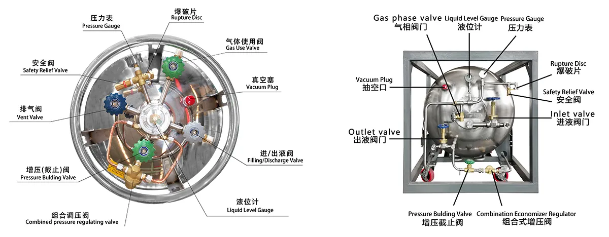
The inner tank and outer shell of the Dewar are made of stainless steel, and the inner tank support system is made of stainless steel to improve strength and effectively reduce heat loss. There is a thermal insulation layer between the inner tank and the outer shell. Multi-layer thermal insulation materials and high vacuum ensure the liquid storage time.
A built-in vaporizer is arranged inside the shell to convert cryogenic liquid into gas, and the built-in supercharger can increase the pressure to a predetermined pressure and keep it stable during use, achieving the purpose of rapid and stable use. Each insulated gas cylinder has a stainless steel ring structure (protection ring) to protect the pipeline. The protective ring is connected to the cylinder with four brackets, and each bracket is slotted to facilitate the use of trolleys and cranes to carry the gas cylinder.
All operating parts are placed on the top of the gas cylinder for easy operation. In an independent use environment, the user can effectively control the use process through the discharge valve, booster valve, pressure gauge, liquid phase valve, etc.
In order to ensure that the inner liner of the gas cylinder is below the safety pressure, a safety valve and a rupture disk are installed on the gas cylinder.
Note: When filling natural gas, use double safety valves and eliminate the rupture disc in the inner tank.
Caution: Adjusting the top screw of the combined pressure regulator does not accelerate the pressurization speed. Adjusting the top pin of the combined pressure regulator at will will result in combined pressure regulation. The valve will be damaged.
Combination Pressure Regulating Valve: This valve has the dual function of pressure regulation and air conservation. When pressurizing, the cryogenic liquid in the cylinder is converted into saturated vapor by the pressurizing coil, and then returned to the gas phase space at the top of the cylinder through this valve, thereby providing a continuous and stable pressure in the cylinder. When using gas, the gas with too high pressure in the gas phase space at the top of the gas cylinder is preferentially discharged to the outside through this valve to avoid gas loss caused by opening the safety valve due to excessive gas pressure. The solar period is automatic without manual operation.
Gas Use Valve: This valve is connected to a built-in vaporizer through which vaporized gas can be obtained. It requires a CGA fitting that matches the gas supplied by the container.
Inlet and outlet valve: This valve is used to control the loading and unloading of cryogenic liquid. The user can connect to the CGA connector in front of the valve through a special hose to perform filling and discharging of gas cylinders.
Booster valve: This valve controls the built-in booster circuit. Open this valve to pressurize the cylinder.
Drain valve: This valve is connected to the gas phase chamber of the cylinder. Opening this valve can release the gas in the cylinder and reduce the pressure.
Pressure Gauge: Shows the pressure of the gas cylinder in pounds per square inch (psi) or megapascals (MPa).
Level Gauge: The cylinder level gauge is a floating-rod spring type gauge that uses the buoyancy of the cryogenic liquid to approximately indicate the cryogenic liquid in the cylinder capacity. However, accurate measurement must be weighed.
Safety device: The cylinder liner is designed with a first stage safety valve and a second stage rupture disc to protect the cylinder in case of overpressure. (In case of overpressure) the safety valve is opened and its function is to release the pressure rise caused by normal heat leakage loss of the insulation layer and support, or the pressure rise caused by accelerated heat leakage after the vacuum of the sandwich layer is broken and under fire conditions. If the safety valve fails, the rupture disk will open to release the pressure to ensure the safety of the cylinder.
Note: When filling with natural gas, use double safety valves and eliminate the bursting disc in the inner tank. Protection of the enclosure under overpressure conditions is provided by a vacuum plug. If the inner tank leaks (resulting in excessive interlayer pressure), the vacuum plug will open to relieve the pressure. If the vacuum plug leaks, the interlayer vacuum is destroyed. At this point, “sweating” and frosting of the shell may occur. Of course, frost or condensation at the end of the tube connected to the cylinder body is normal.
Warning: It is strictly forbidden to pull out the vacuum plug under any circumstances.
Note: Bursting discs can only be used once. The bursting disc must be replaced after it has been used. Can be purchased from our company.