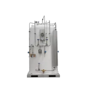
Brief Introduction:
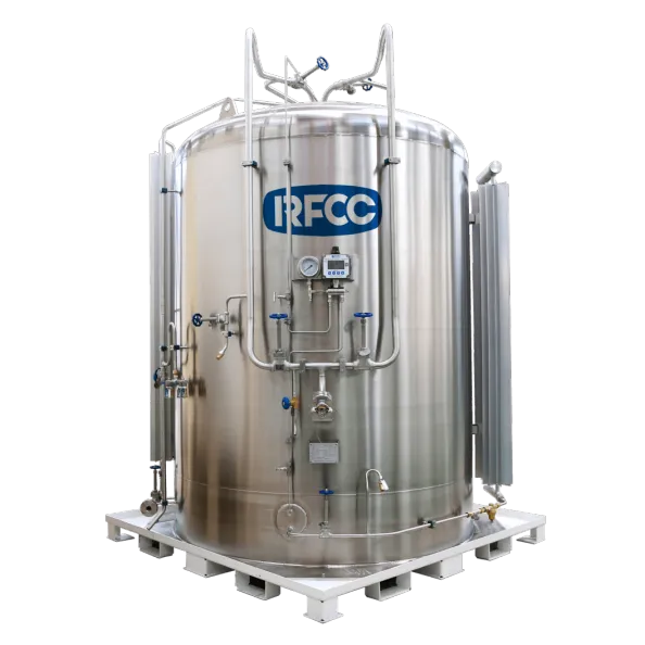
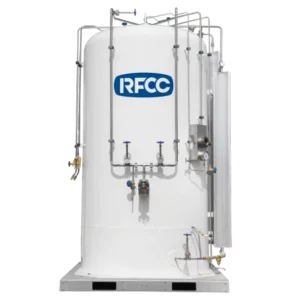
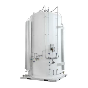
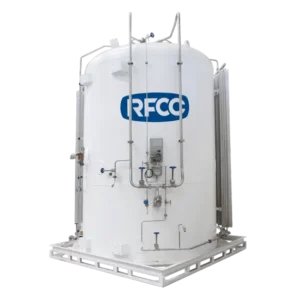
The cryogenic liquid gas storage tank is composed of skid-mounted equipment, cryogenic liquid storage tank and pipeline system. It has the functions of storage, self-pressurization, vaporization, and can be equipped with pressure and liquid level remote transmission, metering and other equipment. Our micro-bulk tank is a combination of small volume storage tank, booster, evaporator and piping system into a centralized gas supply unit. We can provide edifferent solutions of skid based on different process requirements to achieve single, double or multiple gas mixing requirements.
Main Features:
It has Low evaporation rate, small floor area, centralized control and convenient operation. Compared with the traditional high-pressure steel gas cylinder, this product can greatly reduce the number of replacement, pollution and labor cost. This product can be filled by common transportation tanker/semi-trailer, which is convenient and fast. We can provide users with on-site filling integrated solution and let you enjoy the centralized pipeline gas supply.
Micro-bulk Tank Main Technical Parameters:
Full Volume: 1,000L~10,000L
Work Pressure: 2.16MPa
Filling Rate:95%
Inner Tank Design Temperature: -40℃
Shell Tank Design Temperature: -20℃~+50℃
Insulation: Vacuum with Multi-layer Wrapped
Stored Medium: LCO2
Inner Tank Material: 16MnDR
Shell Tank Material: Q345R or SS304 08
Qualification Certification:
ASME VIII DIV.1, CE PED/TPED, Russia EAC, China GB, ISO9001:2015, ISO134852016, ISO14001:2015, ISO45001:2018

Production Information:
| Technical Parameters of microbulk portable tanks | |||||||||||
| Geometric Volume |
Work Pressure (MPa) |
Liquid Gases Weight(kg) | Tare Weight (kg) |
Inner vessel | Outer vessel | Overall Dimensions (mm) |
|||||
| LO2 | LN2 | LAR | LNG | LCO2 | LO2/LN2/LAR/LNG | LCO2 | |||||
| 1 | ≤0.80 | 1083 | 769 | 1339 | 404 | / | 926 | / | SS30408 | SS30408/Q345R | 2085*1580*1160 |
| ≤1.60 | / | 926 | / | ||||||||
| ≤2.30 | / | 926 | / | ||||||||
| ≤3.45 | / | 1040 | / | ||||||||
| ≤2.16 | / | / | / | / | 1059 | / | 1045 | 16MnDR | SS30408/Q345R | ||
| 2 | ≤0.80 | 2017 | 1433 | 2495 | 796 | / | 1398 | / | SS30408 | SS30408/Q345R | 2360*2140*1975 |
| ≤1.60 | / | 1398 | / | ||||||||
| ≤2.30 | / | 1511 | / | ||||||||
| ≤3.45 | / | 1695 | / | ||||||||
| ≤2.16 | / | / | / | / | 1915 | / | 2020 | 16MnDR | SS30408/Q345R | ||
| 3 | ≤0.80 | 3120 | 2192 | 3800 | 1047 | / | 1773 | / | SS30408 | SS30408/Q345R | 2560*2338*2143 |
| ≤1.60 | / | 1810 | / | ||||||||
| ≤2.30 | / | 1993 | / | ||||||||
| ≤3.45 | / | 2246 | / | ||||||||
| ≤2.16 | / | / | / | / | 3166 | / | 2454 | 16MnDR | SS30408/Q345R | ||
| 5 | ≤0.80 | 5403 | 3839 | 6645 | 1917 | / | 2655 | / | SS30408 | SS30408/Q345R | 3086*2331*2325 |
| ≤1.60 | / | 2745 | / | ||||||||
| ≤2.30 | / | 2964 | / | ||||||||
| ≤3.45 | / | 3405 | / | ||||||||
| ≤2.16 | / | / | / | / | 5085 | / | 3527 | 16MnDR | SS30408/Q345R | ||
| 7.5 | ≤0.80 | 8105 | 5759 | 10025 | 3035 | / | 3490 | / | SS30408 | SS30408/Q345R | 3170*2715*2450 |
| ≤1.60 | / | 3581 | / | ||||||||
| ≤2.30 | / | 3904 | / | ||||||||
| ≤3.45 | / | 4550 | / | ||||||||
| ≤2.16 | / | / | / | / | 7950 | / | 5065 | 16MnDR | SS30408/Q345R | ||
| 10 | ≤0.80 | 10830 | 7695 | 13395 | 3834 | / | 4431 | / | SS30408 | SS30408/Q345R | 3950*2840*2800 |
| ≤1.60 | / | 4981 | / | ||||||||
| ≤2.30 | / | 5347 | / | ||||||||
| ≤3.45 | / | 6450 | / | ||||||||
| ≤2.16 | / | / | / | / | 10592 | / | 6640 | 16MnDR | SS30408/Q345R | ||
| Note: The above technical parameters may be changed without prior notice due to modification and development. If there is any change, please refer to the confirmed drawing. | |||||||||||
The structure of the micro-bulk Tank
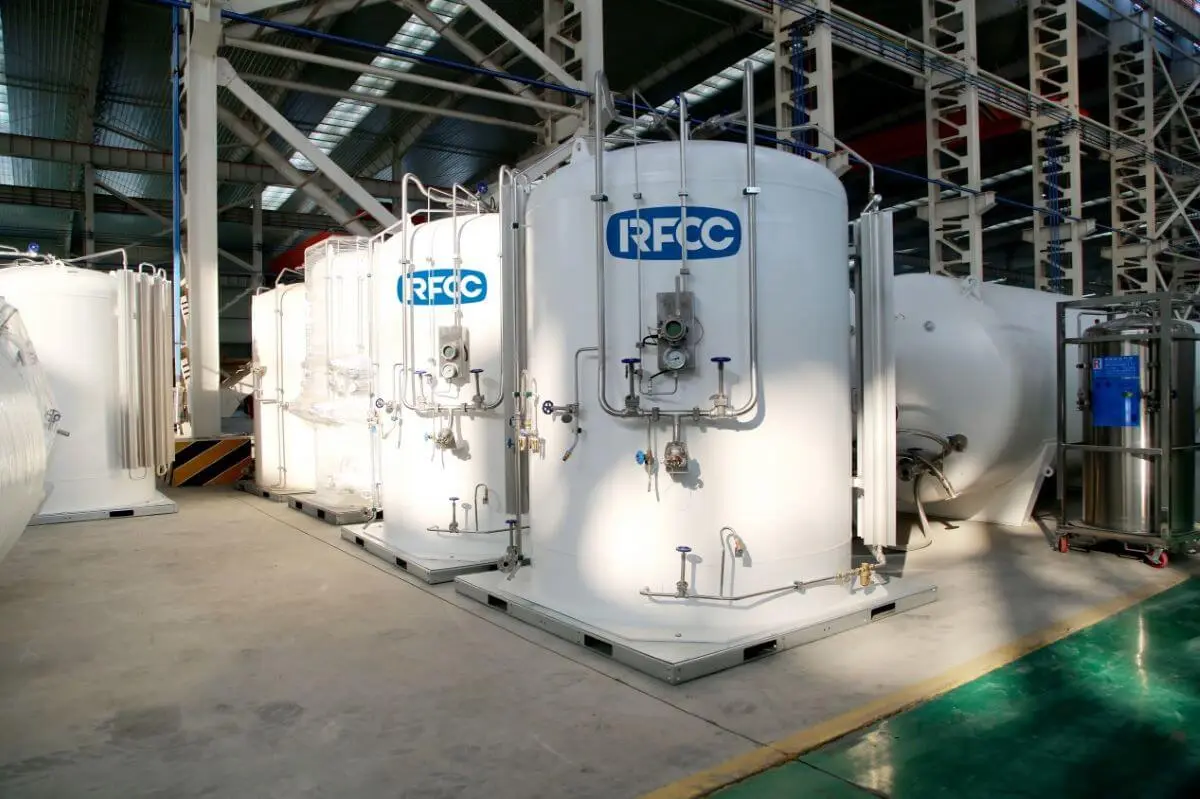
Piping system
The piping system mainly consists of liquid filling piping, pressurizing piping, liquid level meter piping, gas piping, liquid piping, auxiliary gas piping, and discharge piping (LNG).
1. Liquid filling pipeline: This system is mainly composed of top liquid inlet pipeline and bottom filling pipeline, including top liquid inlet shut-off valve (A-2), bottom liquid inlet shut-off valve (A-1), purge valve (A-7) and liquid filling connection device.
2. Pressurized pipeline: the system is a cryogenic liquid from the pressurized liquid inlet pipe connected to the external pipeline of “Ansoda”, through the supercharger input valve, filter, pressurized regulator, the supercharger into gas back to the internal “Ansoda”, make “Ansoda”. The process of self-pressurization is carried out by “ANSHUTA”.
3. Liquid level meter pipeline: composed of differential pressure liquid level meter and pressure gauge, can monitor the liquid level and pressure inside the tank.
4. Gas pipeline: connected with the liquid outlet pipe, when the gas consumption is large, open the gas valve (A-6), the pressure inside the tank will make the liquid enter the vaporizer from the container, and quickly vaporize into gas for customers to use.
5. Liquid pipeline: open the liquid discharge valve (A-13), you can use the cryogenic liquid directly.
6. Auxiliary gas pipeline: connected with the gas phase space in the tank, when the gas consumption is not large, you can directly use the auxiliary gas valve (A-19) to use gas.
7. Gas discharge pipeline: this pipeline is connected with the gas phase space on the top of the inner container, including the venting pipeline and the safety discharge pipeline.
Air vent line: reduces the pressure in the gas phase space and lowers the gauge pressure. When the pressure at the top of the inner packagings is high when the tank is filled, the venting valve is opened to reduce the pressure in the gas phase space at the top of the inner packagings.
Safety Drain Line: An overpressure relief device containing a safety valve and rupture disc to protect the inner packagings.

